The skull has 8 cranial bones and 14 facial bones. Routine skull imaging is a PA axial (Caldwell), an AP axial (Towne) and a lateral; the facial bones and sinuses add the parietoacanthial (Waters) and, when ordered, the submentovertical (SMV).
Overview
Bones
Cranial bones (8)
Frontal
Parietal (2)
Temporal (2)
Occipital
Sphenoid
Ethmoid
Facial bones (14)
Nasal (2)
Lacrimal (2)
Maxillae (2)
Zygomatic (2)
Palatine (2)
Inferior nasal conchae (2)
Vomer
Mandible
Orbit (7 bones form it)
Roof: frontal and lesser wing of the sphenoid
Lateral wall: zygomatic and greater wing of the sphenoid
Floor: maxilla, zygomatic, palatine
Medial wall: ethmoid, lacrimal, maxilla, sphenoid
Supraorbital, infraorbital and lateral orbital margins
Openings: optic canal, superior and inferior orbital fissures
Orbit cone points posteriorly, 37° from the MSP and 30° up from the OML (why the Rhese angles work: MSP 53°, AML perpendicular)
Glabella, nasion, acanthion, mental point, gonion, EAM
OML: outer canthus to EAM
IOML: infraorbital margin to EAM (7° from the OML)
MML: mentum to EAM · LML: lips to EAM
IPL: line between the pupils · MSP: midsagittal plane
The OML and IOML are 7° apart, so a CR angle changes by 7° with the baseline: Towne is 30° caudad to the OML or 37° to the IOML.
Registry must-knows
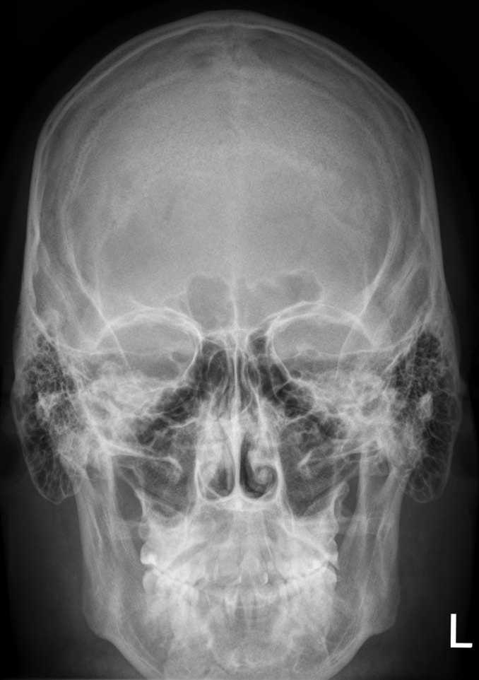
PA with no angle: the petrous ridges fill the orbits. Caldwell (15° caudad): they drop into the lower third of the orbits.
Towne: the dorsum sellae and posterior clinoid processes project within the foramen magnum.
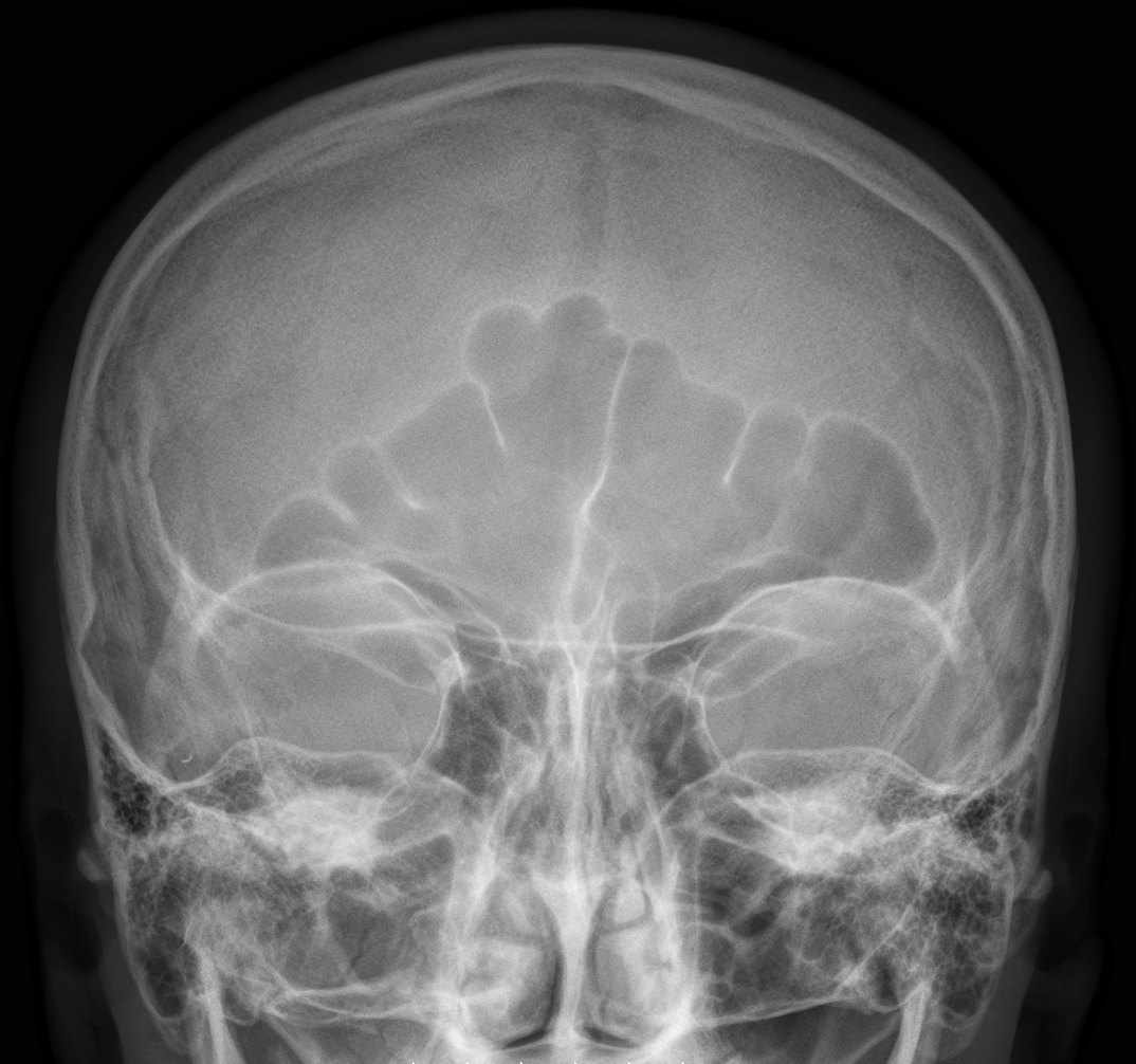
Waters: the petrous ridges project just below the maxillary sinuses. An open-mouth Waters also shows the sphenoid sinus.
Lateral skull: MSP parallel and IPL perpendicular to the IR, so the orbital roofs, mandibular rami and EAMs superimpose and the sella turcica is in profile.
Show 3 more
Sinus series: always erect with a horizontal beam so air-fluid levels show.
Rotation check on frontal views: equal distance from the lateral orbital margin to the lateral border of the skull on both sides.
Mastoid air cells and the EAM are best on the lateral; the petrous ridges and IAMs are judged on the frontal and axial views.
3D model
Loading 3D…
Radiographs 15
Pick a film, then a structure to circle it.
PA axial (Caldwell)Image: Hellerhoff. CC BY-SA 3.0. Source
Mandibular condyles projected anterior to the petrous ridges.
Mandibular symphysis superimposed over the frontal bone.
Equal distance from the mandible to the lateral skull borders (no tilt).
Modified parietoacanthial (orbits)
Modified WatersCR: Perpendicular
Position
Chin and nose on the IR, OML 55° to the IR (less extension than a Waters); LML about perpendicular.
Central ray
Perpendicular
Centering
Exits at the acanthion (mid-orbits)
Typical technique
75–80 kVp · 10–20 mAs · 40" SID
Best shows
Orbital floors (blowout fractures) and orbital rims
Image criteria
Petrous ridges in the lower half of the maxillary sinuses, below the orbital floors.
Orbits fully shown and symmetric (no rotation).
Parieto-orbital oblique (optic canal)
RheseCR: Perpendicular
Position
Prone or erect, zygoma, nose and chin on the IR (three-point landing); MSP 53° to the IR, AML perpendicular. Side of interest down; do both sides.
Central ray
Perpendicular
Centering
Through the downside orbit
Typical technique
75–80 kVp · 10–15 mAs · 40" SID
Best shows
Optic canal (foramen) seen end-on in the lower outer quadrant of the orbit
Image criteria
Optic canal in the lower outer quadrant of the orbit (too far out or in means wrong rotation; too high or low means wrong AML).
Entire orbital rim shown.
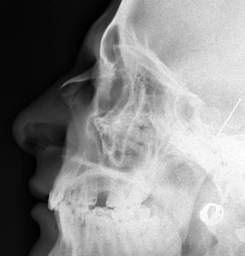
Lateral nasal bones
CR: Perpendicular
Position
Lateral, MSP parallel to the IR, IPL perpendicular, IOML parallel to the transverse axis of the IR. Both sides are usually done.
Central ray
Perpendicular
Centering
1/2 in (1.25 cm) distal to the nasion
Typical technique
60–65 kVp · 2–4 mAs · 40" SID
Best shows
Nasal bones and soft tissue of the nose, frontonasal suture and anterior nasal spine
Image criteria
Nasal bones in profile with no rotation.
Soft tissue of the nose shown (low technique, detail).
PA mandible
CR: Perpendicular
Position
Forehead and nose on the IR, OML perpendicular, MSP perpendicular.
Central ray
Perpendicular
Centering
Exits at the junction of the lips
Typical technique
75–80 kVp · 8–15 mAs · 40" SID
Best shows
Rami and lateral parts of the body
Image criteria
Rami and body symmetric on both sides (no rotation).
Mandibular body and rami fully included.
PA axial mandible
CR: 20–25° cephalad
Position
As for the PA mandible: forehead and nose on the IR, OML perpendicular.
Central ray
20–25° cephalad
Centering
Exits at the acanthion
Typical technique
75–80 kVp · 8–15 mAs · 40" SID
Best shows
Condyles and rami; condyles elongated, just below the mastoid processes
Image criteria
Condyles shown, just below the mastoid processes.
Rami symmetric (no rotation).
Axiolateral oblique mandible
CR: 25° cephalad
Position
Lateral, side of interest against the IR, neck extended. Head turned toward the IR: 0° (true lateral) for the ramus, 30° for the body, 45° for the symphysis.
Central ray
25° cephalad
Centering
Exits at the mandibular region of interest
Typical technique
70–80 kVp · 8–12 mAs · 40" SID
Best shows
One side of the mandible (ramus, body or symphysis) free of the other side
Image criteria
Area of interest free of superimposition from the opposite side.
Ramus not superimposed on the cervical spine.
Technique values are typical starting points; follow your department's technique chart.
Labeled diagrams
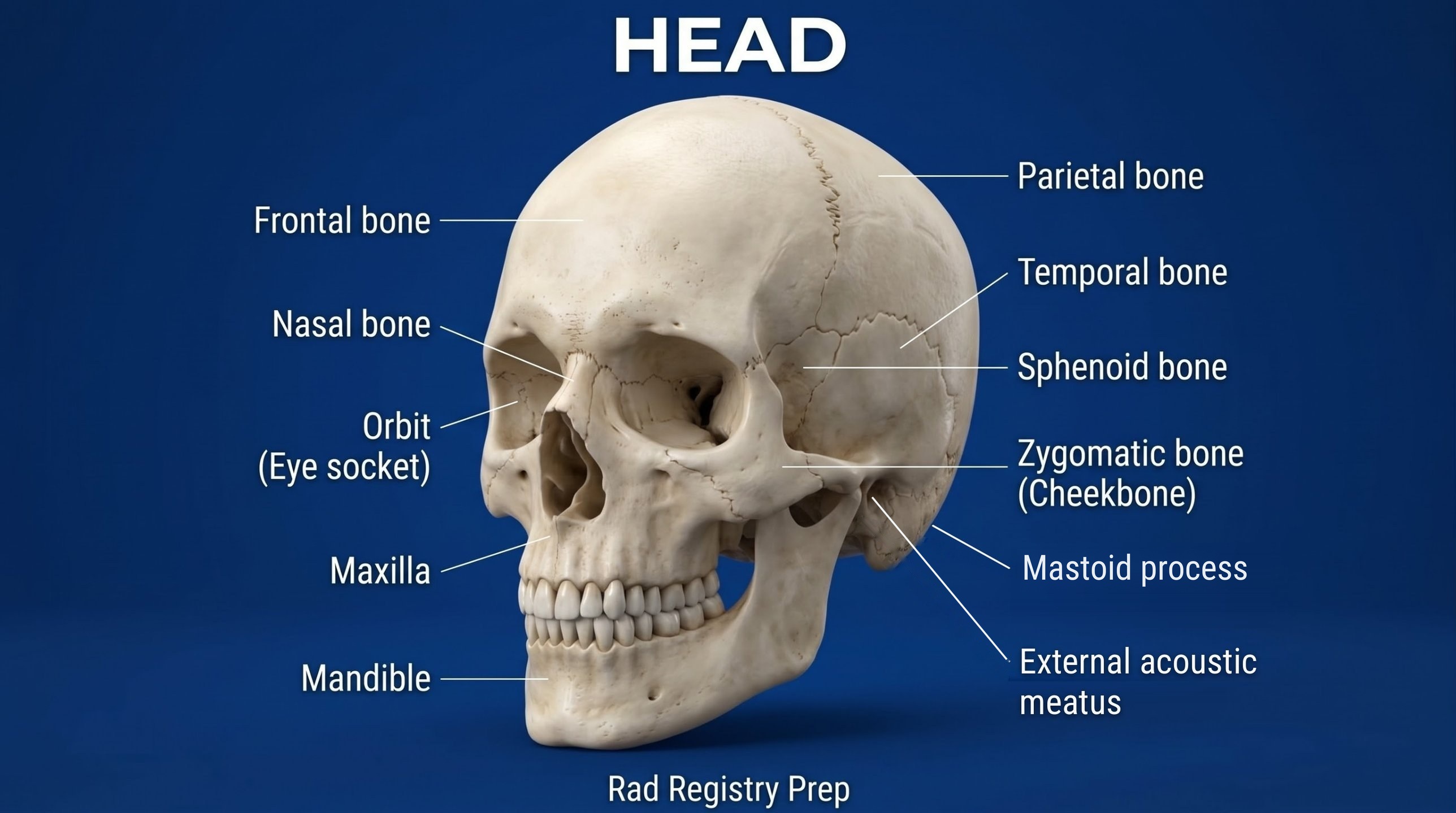
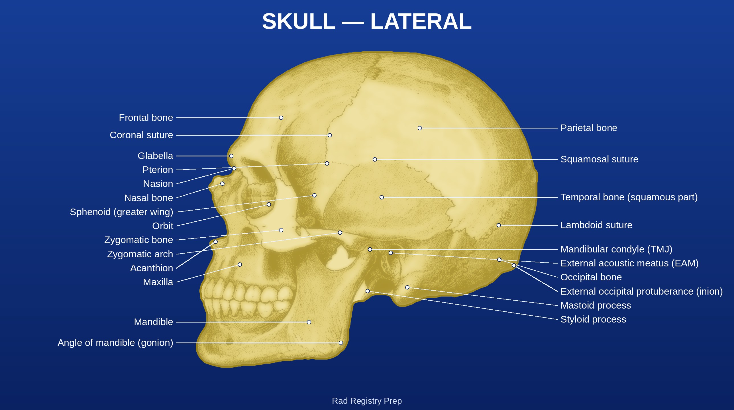
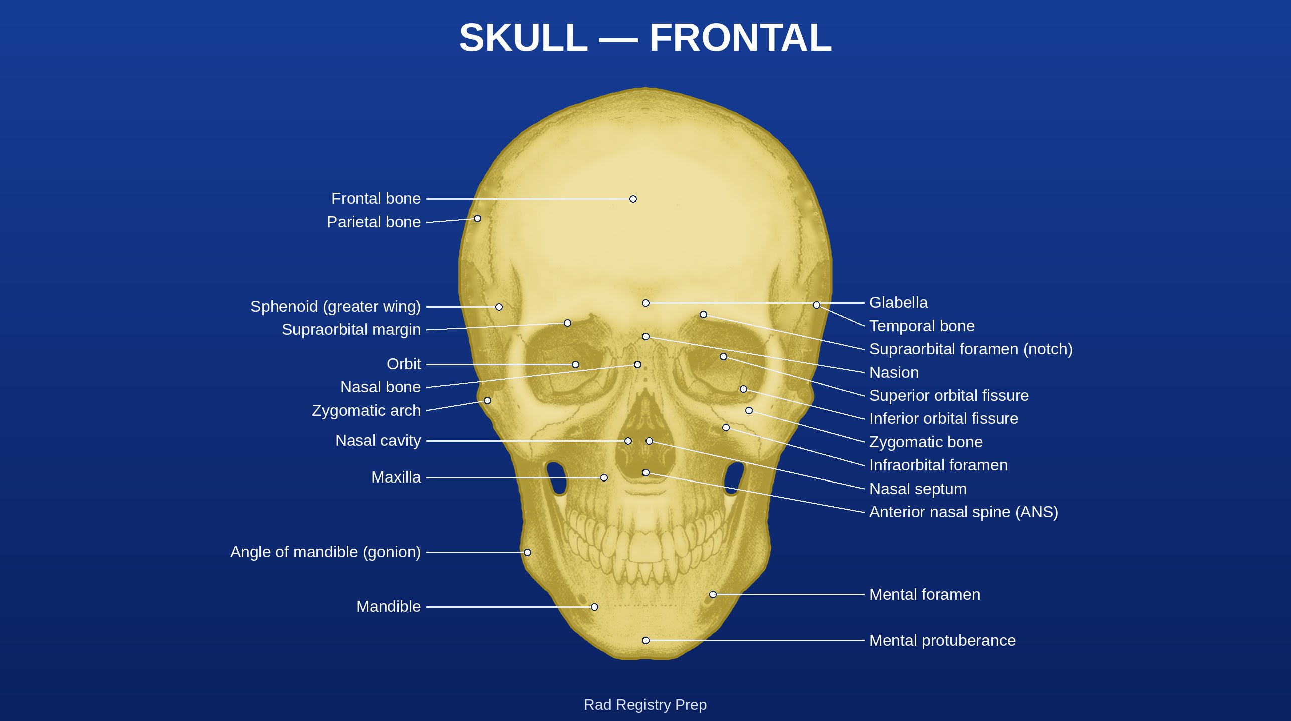
Skull (anterolateral view) · Diagram: Rad Registry Prep (original illustration).Skull: Lateral (Sutures and Ear) (lateral view) · Diagram: Rad Registry Prep, restyled and labeled from Gray's Anatomy (1918), public domain.Skull: Frontal (Orbits and Face) (anterior view) · Diagram: Rad Registry Prep, restyled and labeled from Gray's Anatomy (1918), public domain.
Quick check
1. Which projection of the skull is shown on this radiograph?
Image: Hellerhoff. CC BY-SA 3.0.
2. Why should projections of the paranasal sinuses be taken with the patient erect and a horizontal CR whenever possible?
3. Before a submentovertex (SMV) projection of the cranial base is attempted on a trauma patient, which condition must be ruled out?
4. For lateral nasal bone projections like this one, which technique and comparison are used?
Image: Nevit Dilmen, via Wikimedia Commons. CC BY-SA 3.0.
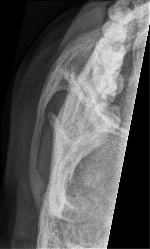
5. This unilateral image projects one zygomatic arch free of the skull. How is this tangential (May-type) projection positioned?