The cervical spine has 7 vertebrae; C1 (atlas) and C2 (axis, with the dens) are atypical. A routine C-spine is an AP axial, an open-mouth (C1–C2), a lateral and often obliques.
Overview
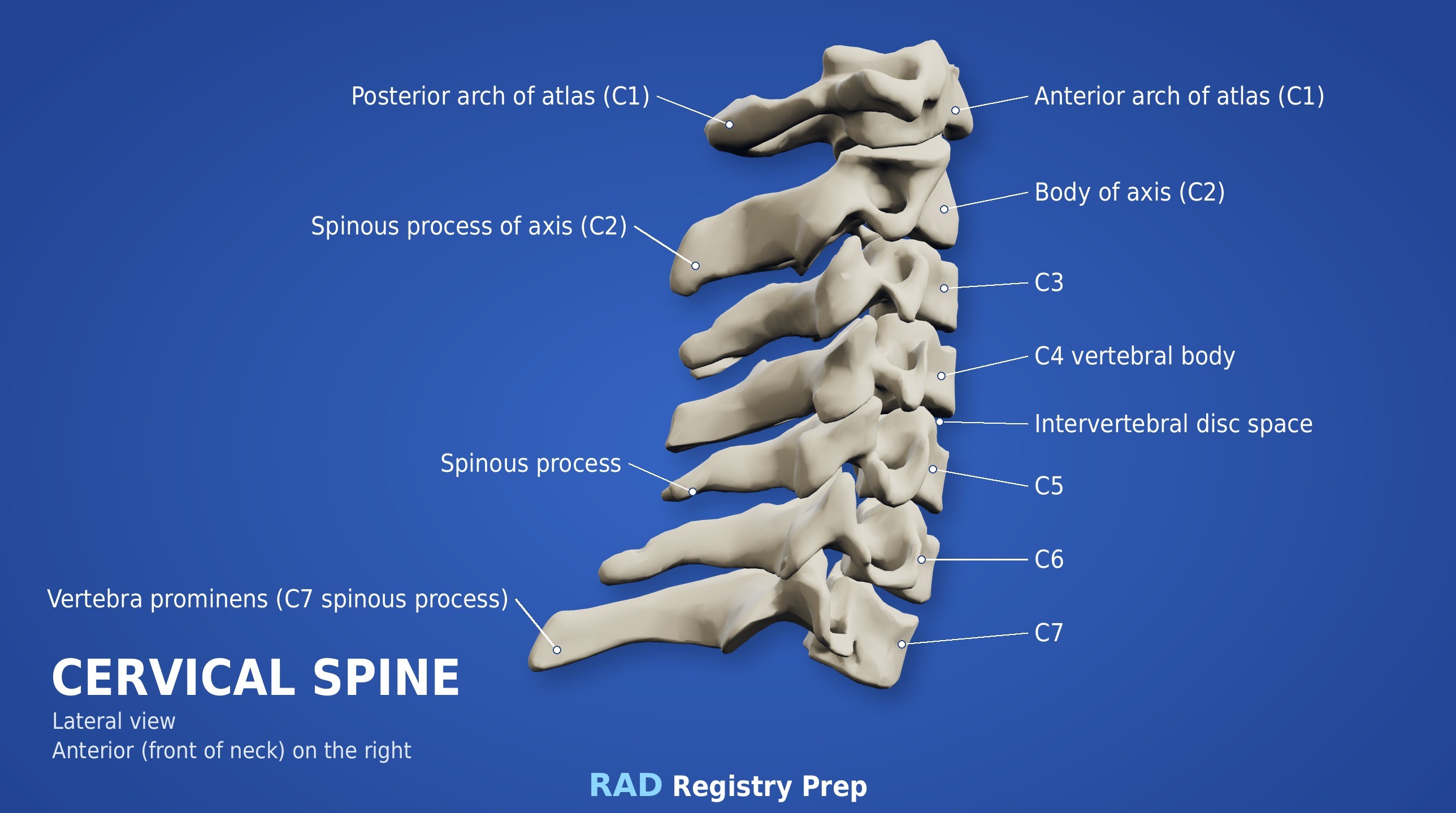
Bones
Atypical
C1 (atlas): no body, lateral masses
C2 (axis): dens (odontoid process)
C7: vertebra prominens
Typical (C3–C6)
Body
Bifid spinous process
Transverse foramina
Zygapophyseal joints (best on the lateral)
Intervertebral foramina (best on obliques, 45°)
C-spine foramina open at 45° and are seen on the obliques; zygapophyseal joints are seen on the lateral (90°).
Registry must-knows
Trauma: the cross-table lateral comes first and must be cleared before moving the patient. All 7 vertebrae and the top of T1 must be seen.
Lateral C-spine: 72-inch SID reduces magnification from the large OID; depress the shoulders (weights or traction) to see C7.
If C7–T1 still isn't shown, use the swimmer's (Twining) lateral.
Open-mouth: line the occlusal plane and the mastoid tips up so the upper teeth and skull base don't hide the dens.
Show 1 more
Posterior obliques (RPO/LPO) with a 15–20° cephalad CR show the foramina farthest from the IR; anterior obliques with a caudal CR show those closest.
3D model
Loading 3D…
Radiographs 5
Pick a film, then a structure to circle it.
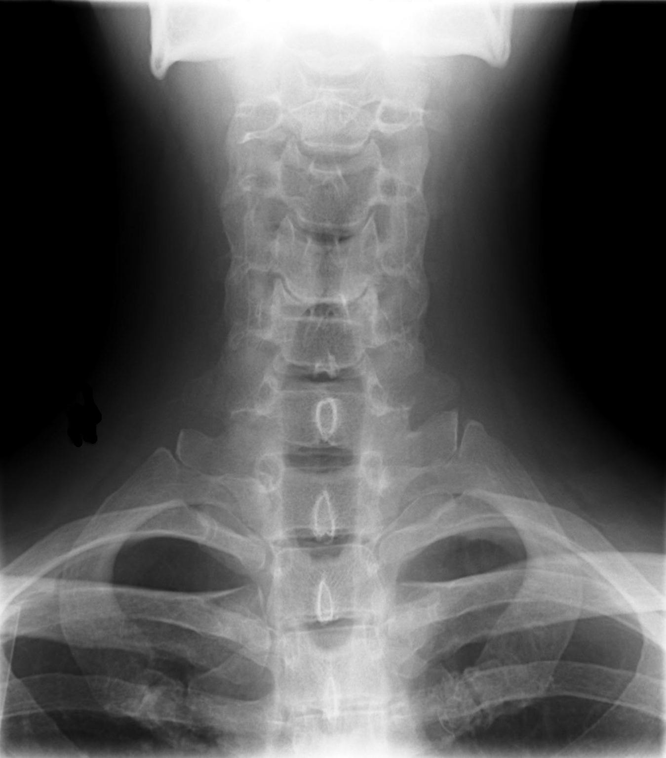
AP axial C-spineImage: Stillwaterising. CC0 1.0. Source
Erect or supine, MSP centered, chin raised so a line from the lower edge of the upper incisors to the mastoid tip is perpendicular to the IR.
Central ray
15–20° cephalad
Centering
C4 (at the thyroid cartilage)
Typical technique
75–80 kVp · 8–12 mAs · 40" SID
Image criteria
C3 through T2 seen; disk spaces open.
Spinous processes equidistant from the pedicles; no rotation.
Mandible superimposed over the occipital base and C1–C2.
AP open mouth (C1–C2)
CR: Perpendicular
Position
Mouth open as wide as possible; lower edge of the upper incisors and the mastoid tips aligned perpendicular to the IR.
Central ray
Perpendicular
Centering
Center of the open mouth
Typical technique
75–80 kVp · 10–16 mAs · 40" SID
Best shows
The dens and the lateral masses of C1 on C2
Image criteria
Dens and C1–C2 articulations seen through the open mouth.
Upper incisors and skull base clear of the dens.
Equal spaces between the dens and the lateral masses (no rotation).
Lateral C-spine
CR: Perpendicular
Position
Erect, left side against the IR, shoulders depressed, chin slightly raised.
Central ray
Perpendicular
Centering
C4 (thyroid cartilage)
Typical technique
75–80 kVp · 10–16 mAs · 60–72" SID
Image criteria
C1 through the top of T1 included.
Zygapophyseal joints open; no rotation (posterior bodies superimposed).
Mandible clear of C1–C2.
AP axial oblique (posterior oblique)
RPO / LPOCR: 15–20° cephalad
Position
Body rotated 45° (posterior oblique), head turned to the side.
Central ray
15–20° cephalad
Centering
C4
Typical technique
75–80 kVp · 10–16 mAs · 60–72" SID
Best shows
Intervertebral foramina and pedicles farthest from the IR
Image criteria
Intervertebral foramina open (C2–C3 to C7–T1).
Pedicles in profile.
Mandible clear of the upper vertebrae.
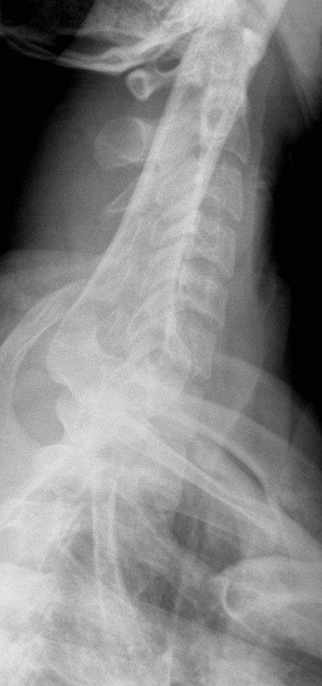
Cervicothoracic lateral (swimmer's)
TwiningCR: Perpendicular, or 3–5° caudad if the far shoulder can't be depressed
Position
Left lateral (erect or recumbent). Arm next to the IR raised overhead; the other shoulder depressed and moved slightly posterior to separate the humeral heads.
Central ray
Perpendicular, or 3–5° caudad if the far shoulder can't be depressed
Centering
T1 (C7–T1): about 1 inch above the jugular notch anteriorly, at the vertebra prominens posteriorly
Typical technique
75–85 kVp · 20–40 mAs · 60–72" SID
Best shows
C7–T1 when the shoulders hide it on the routine lateral
Image criteria
C7–T1 interspace seen between the humeral heads.
Vertebral bodies and disk spaces of C5–T3 in lateral view.
Humeral heads separated vertically, not superimposed on C7–T1.
Technique values are typical starting points; follow your department's technique chart.
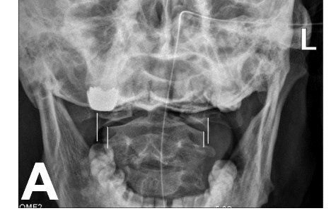
1. The offset of the C1 lateral masses relative to C2, marked by the lines on this AP open-mouth radiograph, is most consistent with which pathology?
Image: Tu, Chen, Li, et al. CC BY 4.0.
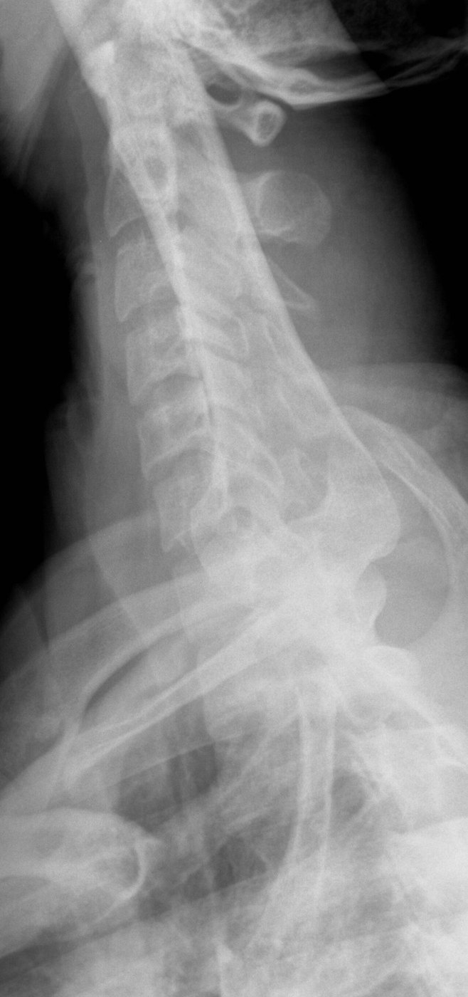
2. Which patient positioning produces this cervicothoracic (swimmer's) lateral projection?
Image: Staff at the Department of Radiology, UC San Diego Health. Public domain.
3. For AP axial oblique (posterior oblique) projections of the cervical spine, the patient is rotated 45 degrees. How is the CR directed?
4. A patient with long-standing rheumatoid arthritis is scheduled for lateral cervical spine projections in flexion and extension. Which risk should the radiographer keep in mind when guiding the movement?
5. This cervicothoracic (swimmer's) lateral was taken to see C7 and T1. Where is the CR centered?
Image: Staff at the Department of Radiology, UC San Diego Health, via Wikimedia Commons. Public domain.