
Image Production · Equipment, AEC and QC2 min read5-question check
X-ray Circuit and Generators
The step-up transformer sets kVp, the filament circuit sets mA, and less voltage ripple means more beam per mAs.
The main circuit
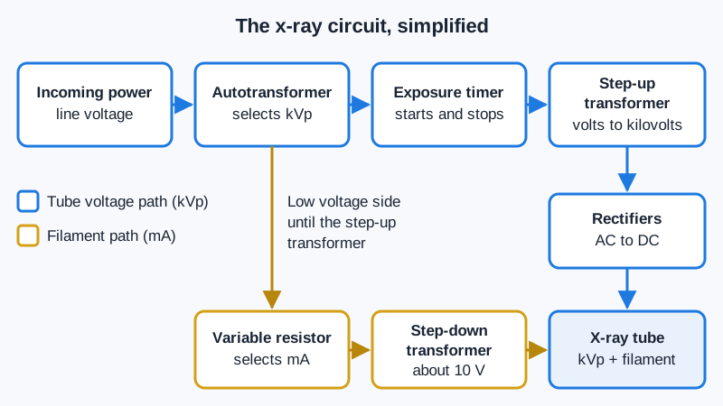
The x-ray circuit turns wall power into the high voltage and filament current the tube needs. Power first reaches the autotransformer, a single-winding transformer whose taps let you select kVp. The exposure timer starts and stops the exposure. The step-up transformer then raises the voltage from hundreds of volts to tens of thousands. Rectifiers, which are solid-state diodes, change alternating current to direct current so electrons flow only from cathode to anode.
The x-ray circuit, simplified
The filament circuit
A separate filament circuit sets tube current. A variable resistor controls how much current reaches a step-down transformer. The step-down transformer lowers the voltage to about 10 volts and raises the current to a few amperes. That current heats the filament, and thermionic emission boils off electrons. More filament heat means more electrons, so this circuit controls mA. Keep the pairing straight: step-up transformer for kVp, step-down transformer for mA.
The numbers
Transformers change voltage in proportion to their turns ratio. A step-up transformer with a 500:1 ratio turns 200 volts into 100,000 volts, or 100 kV. Voltage ripple is how far the voltage drops between peaks. Single-phase power has 100% ripple, so a 100 kVp exposure swings from 0 to 100 kV. Three-phase 6-pulse has about 13 to 14% ripple, so the voltage never falls below about 86 kV. Three-phase 12-pulse has about 3 to 4%. High-frequency generators have less than 1%.
Why ripple matters
Less ripple keeps the voltage near its peak for the whole exposure. The average photon energy rises, and the tube makes more photons for each mAs. The beam is more penetrating and more intense than a single-phase beam at the same settings. That is why a high-frequency unit needs less mAs for the same receptor exposure and allows shorter exposure times. Almost all new fixed and mobile units are high frequency.
Clinical Example
Your department replaces an old single-phase room with a high-frequency generator. Techniques copied from the old chart produce exposure indicators well above target. The chart is rebuilt with lower mAs values, and patient dose drops with no loss of image quality.
Common Mistakes
- Mixing up the transformers: the step-up sets kVp, the step-down feeds the filament.
- Thinking the autotransformer controls mA; it selects kVp.
- Reading less ripple as a lower kVp; the peak is the same, the average is higher.
- Assuming rectifiers raise voltage; they only change AC to DC.
Why It Matters
The registry asks which component does which job and how generator type affects beam quality and quantity. Knowing ripple values explains why technique charts differ between rooms.
Key Relationships
- Autotransformer → selects kVp
- Step-up transformer → kilovolts across the tube
- Variable resistor and step-down transformer → filament heat → mA
- Less ripple → higher average energy → more output per mAs